To begin to make things interactive, we can learn to use digital and analog inputs to control our circuits. On the Arduino, the digital pins (0 - 13) can only represent two different states: ON or OFF, 1 or 0. Although they can do so quickly (as when they are used for Pulse Width Modulation), ON or OFF is all that they can do! When we think of ON/OFF states, we often think of a button or a switch. We will begin using a button here.
The second set of pins on the Arduino (A0 - A5) are analog. These are able to accept a range of values, meaning that they aren’t either on or off, they can take inputs that say that something is “on a little bit” or “WAY on”. Think of a knob that you can turn to adjust how dim or bright a light is -- there is OFF, ON and a range of values in-between. There are many types of analog sensors that we can use -- from measuring brightness to temperature to the distance that someone is standing from an object. In this starter demo, we will look at using a light sensor as an analog input.
On/Off - 1/0
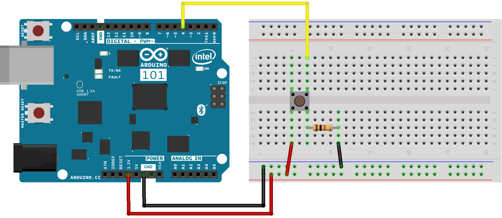
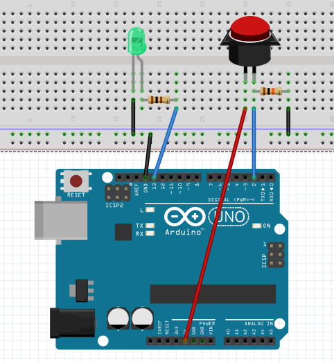
Here is a basic circuit:
/* Basic Digital Read
 * ------------------
 *
 * turns on and off a light emitting diode(LED) connected to digital
 * pin 13, when pressing a pushbutton attached to pin 4. It illustrates the
 * concept of Active-Low, which consists in connecting buttons using a
 * 1K to 10K pull-up resistor.
 *
 * Created 1 December 2005
 * copyleft 2005 DojoDave
 * http://arduino.berlios.de
 *
 */

int ledPin = 13; // choose the pin for the LED
int inPin = 4;   // choose the input pin (for a pushbutton)
int val = 0;     // variable for reading the pin status

void setup() {
  pinMode(ledPin, OUTPUT);  // declare LED as output
  pinMode(inPin, INPUT);    // declare pushbutton as input
}

void loop(){
  val = digitalRead(inPin);  // read input value
  if (val == HIGH) {         // check if the input is HIGH (button released)
    digitalWrite(ledPin, LOW);  // turn LED OFF
  } else {
    digitalWrite(ledPin, HIGH);  // turn LED ON
  }
}

more info about pull-up resistor here.
On/Off - 1/0
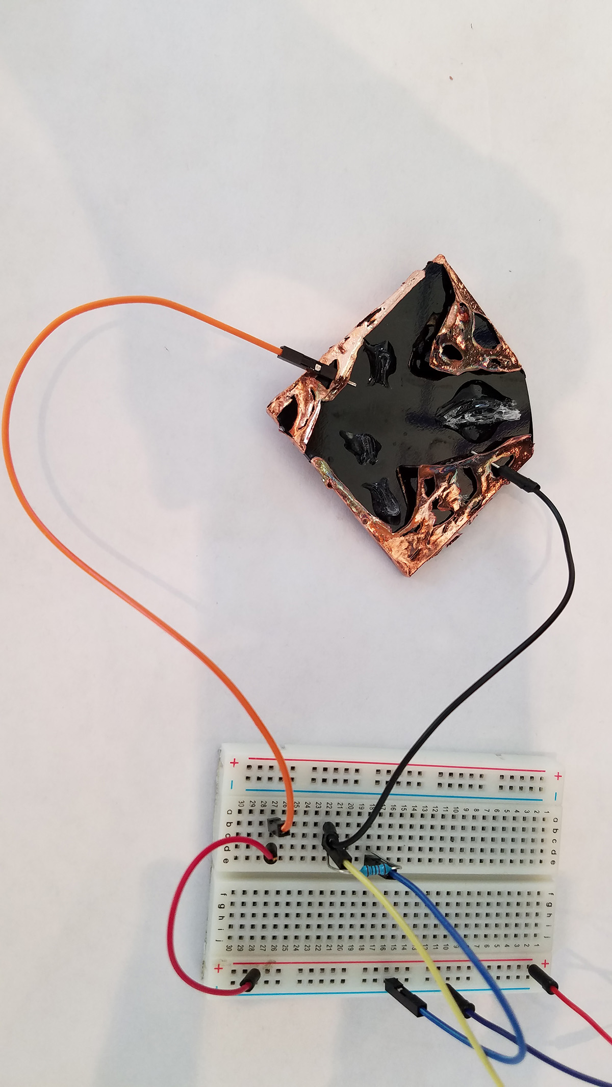
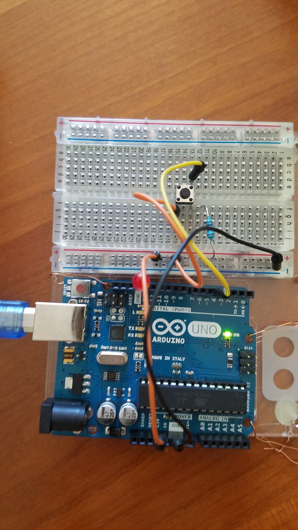
Here is the circuit, but you can replace the 2-prong button with 2 wires, which can then be connected to aluminum foil or another conductive material, such as electroformed copper:
The code is the same as the basic digital read above.
The two leg button transitions us toward using sculptural materials attached to our Arduino instead of an "out-of-the-box" button.
Here, we are using a simple small push-button from your kit, but a button can be many, many things! This is where conductive materials, glass and even human touch can come in to play as you make your projects and incorporate your own ideas of interactivity. You can use conductive materials, such as copper or aluminum foil to make a button. Think about creating two conductive surfaces and holding them apart with foam or another spacer, then allowing someone to press or even step on them.
For a more complex tutorial showing how to check how many times a button has been pushed, click here
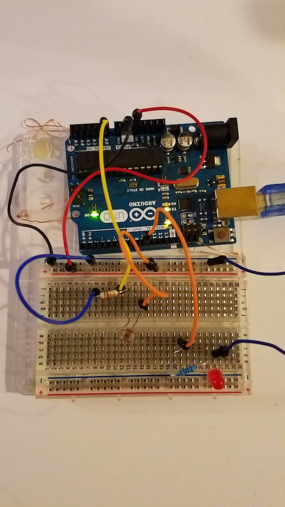
Back to TopNext, we will look at using a basic analog input, a light sensor (called a photocell/photoresistor), to read values into our Arduino circuit and light up an LED in the dark. Next, we can use it to make a light theremin with our Arduino.
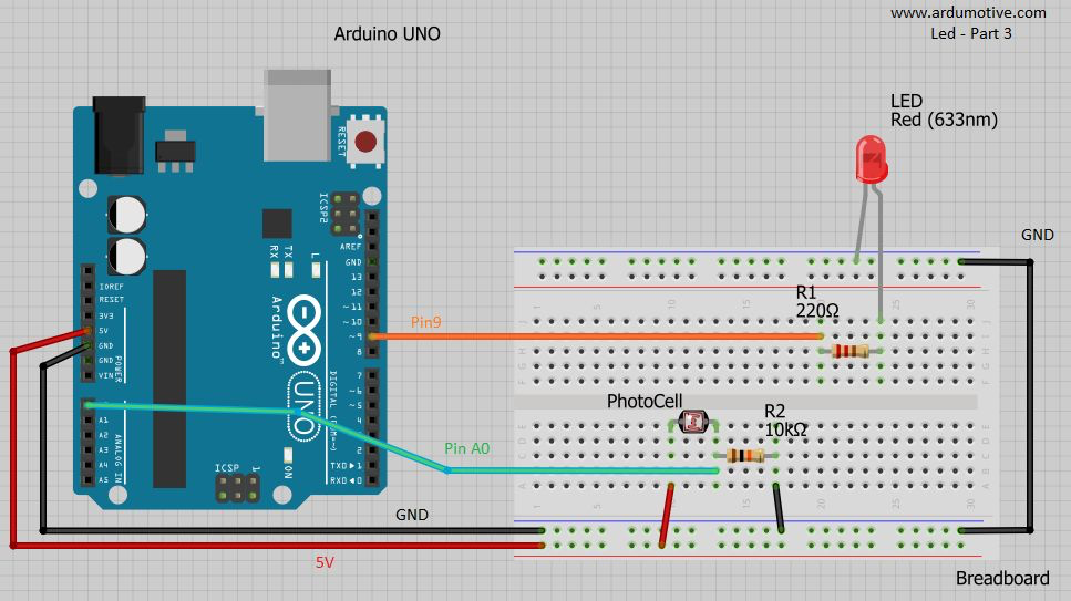
Here is a basic circuit:
/* Use a photoresistor (or photocell) to turn on an LED in the dark
   More info and circuit schematic: http://www.ardumotive.com/how-to-use-a-photoresistor-en.html
   Dev: Michalis Vasilakis // Date: 8/6/2015 // www.ardumotive.com
   Edited by Victoria Bradbury 6/6/2019 */


//Constants
const int pResistor = A0; // Photoresistor at Arduino analog pin A0
const int ledPin=9;       // Led pin at Arduino pin 9

//Variables
int value;          // Store value from photoresistor (0-1023)

void setup(){
  Serial.begin(9600); //allows us to write to the Serial Monitor

 pinMode(ledPin, OUTPUT);  // Set lepPin - 9 pin as an output
 pinMode(pResistor, INPUT);// Set pResistor - A0 pin as an input (optional)
}

void loop(){
  value = analogRead(pResistor);

  Serial.println(value); //prints the analog read of the light sensor to the Serial Monitor

  //You can change value "25"
  if (value > 25){
    digitalWrite(ledPin, LOW);  //Turn led off
  }
  else{
    digitalWrite(ledPin, HIGH); //Turn led on
  }

  delay(150); //Small delay so serial write is easier to read
}
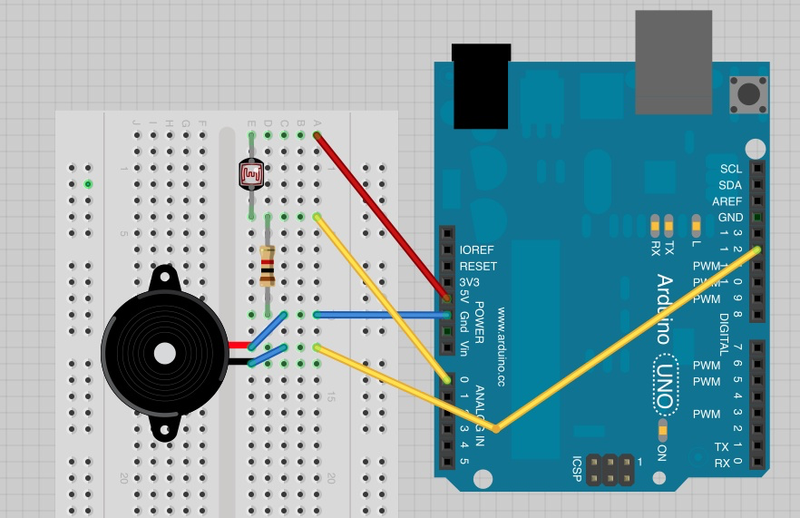
Let’s try adding a piezo speaker and making an Arduino theremin.
/*
Adafruit Arduino - Lesson 10. Pseudo Thermin
By Simon Monk  2012
*/

int speakerPin = 12;
int photocellPin = 0;

void setup()
{
}

void loop()
{
  int reading = analogRead(photocellPin);
  int pitch = 200 + reading / 4;
  tone(speakerPin, pitch);
}